File:1896 Marconi patent.gif
1896_Marconi_patent.gif (582 × 383 pixels, file size: 18 KB, MIME type: image/gif, 0.2 s)
Captions
Captions
| Description1896 Marconi patent.gif |
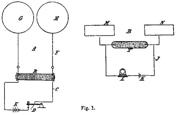
English: In this diagram A is the transmitting instrument and B is the receiving instrument, placed at say ¼ mile apart. In the transmitting instrument R is an ordinary induction coil (a Ruhmkorff coil or transformer). Its primary circuit C is connected through a key D to a battery E, and the extremities of its secondary circuit F are connected to two insulated spheres or conductors G H fixed at a small distance apart. When the current from the battery E is allowed to pass through the primary of the induction coil, sparks will take place between the spheres G H, and the space all around the spheres suffers a perturbation in consequence of these electrical rays or surgings. The arrangement A is commonly called a Hertz radiator, and the effects which propagate through space Hertzian rays. The receiving instrument B consists of a battery circuit J, which includes a battery or cell K, a receiving instrument L, and a tube T containing metallic powder or filings, each end of the column of filings being also connected to plates or conductors M N of suitable size, so as to be preferably tuned with the length of wave of the radiation emitted from the transmitting instruments. The tube containing the filings may be replaced by an imperfect electrical contact, such as two unpolished pieces of metal in light contact, or coherer, &c. The powder in the tube T is, under ordinary conditions, a non-conductor of electricity, and the current of the cell K cannot pass through the instrument; but when the receiver is influenced by suitable electrical waves or radiation the powder in the tube T becomes a conductor (and remains so until the tube is shaken or tapped), and the current passes through the instrument. Français : Dans ce schéma A est l'instrument de transmission et B est l'instrument de réception, mis à part dire ¼ mile. Dans les appareils d'émission R est une bobine d'induction ordinaire (une bobine de Ruhmkorff ou transformateur). Sa C du circuit primaire est connecté via une clé D à un E de la batterie, et les extrémités de ses F circuit secondaire sont connectés à deux sphères isolées ou GH conducteurs fixé à une petite distance. Lorsque le courant de la batterie E est autorisé à passer par le primaire de la bobine d'induction, des étincelles se tiendra entre les sphères GH, et l'espace tout autour de la sphère subit une perturbation à la suite de ces rayons électriques ou surgings. Le schéma A est communément appelé un radiateur Hertz, et les effets qui se propagent dans l'espace hertzien rayons. L'appareil récepteur B se compose d'un circuit de batterie J, qui comprend une batterie ou pile K, un instrument de réception de L, et un tube T contenant de la poudre métallique ou dépôts, chaque extrémité de la colonne de dépôts étant également reliés à des plaques ou des conducteurs de MN taille appropriée, de manière à être à l'écoute de préférence avec la longueur d'onde du rayonnement émis par les instruments de transmission. Le tube contenant les documents peuvent être remplacés par un contact imparfait électriques, tels que deux pièces de métal mat en léger contact, ou cohéreur, & c. La poudre dans le tube T est, dans des conditions normales, un non-conducteur de l'électricité, et le courant de la cellule K ne peut pas passer à travers l'instrument, mais lorsque le récepteur est influencée par appropriés ondes électriques ou de radiations de la poudre dans le tube T devient un chef d'orchestre (et le demeure jusqu'à ce que le tube est secoué ou taraudé), et le courant passe à travers l'instrument. |
|||||
| Date | ||||||
| Source | http://www.radiomarconi.com/marconi/popov/pat763772.html | |||||
| Author | Guglielmo Marconi, 1874 - 1937 | |||||
| Permission (Reusing this file) |
|
|||||
File history
Click on a date/time to view the file as it appeared at that time.
| Date/Time | Thumbnail | Dimensions | User | Comment | |
|---|---|---|---|---|---|
| current | 22:30, 24 March 2009 |  | 582 × 383 (18 KB) | Pieter Kuiper (talk | contribs) | {{Information |Description={{en|1= In this diagram A is the transmitting instrument and B is the receiving instrument, placed at say ¼ mile apart. In the transmitting instrument R is an ordinary induction coil (a Ruhmkorff coil or transformer). I |
You cannot overwrite this file.
File usage on Commons
There are no pages that use this file.
File usage on other wikis
The following other wikis use this file:
- Usage on fa.wikipedia.org
