File:HEPA Filter diagram fr.svg

Size of this PNG preview of this SVG file: 607 × 544 pixels. Other resolutions: 268 × 240 pixels | 536 × 480 pixels | 857 × 768 pixels | 1,143 × 1,024 pixels | 2,285 × 2,048 pixels.
Original file (SVG file, nominally 607 × 544 pixels, file size: 376 KB)
Captions
Captions
Add a one-line explanation of what this file represents
| Description |
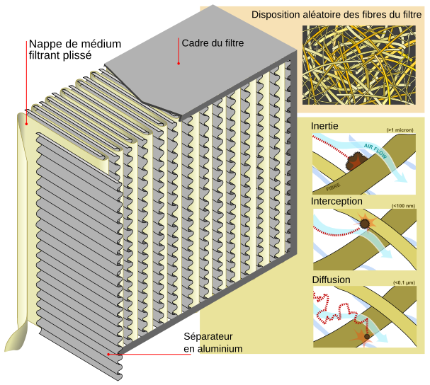
English: diagram showing the main parts of a HEPA filter on the large diagram; its operation is shown on the 3 smaller diagrams: *the thick brown/tan lines represent fibers in the filter medium. *the blue lines represent air flow. *The dark circle represents a particle (dust, bacteria, spore, etc.) *the dotted red line represents the trajectory of the particle; consider that as soon as a particle comes within one radius of a fibre it adheres to it. *in the case of diffusion, the particle (usually 0.1 µm or smaller) has such a trajectory because of the collision with gas molecules. On the 100 nm to 1 micron scales that are the most challenging for filters, it is helpful to think of air as a viscous fluid like molasses. As the fluid flows through the filters, particles are carried around the fibers of the filter medium, for the most part. Inertial impaction: Larger particles (>1 micron) may be massive enough to continue to move in nearly a straight line (Newton's Law), as the flow is diverted around a fiber. Interception: Smaller particles are not much affected by inertia, but, if they are carried within one particle radius of the fiber, they will be intercepted by it. Diffusion: Still smaller particles (<100 nm) move randomly among streamlines as they are buffeted by collisions with molecules. A particle along a streamline that approaches a fiber very closely may be knocked against the fiber by such a collision. English: This image was created as part of the Philip Greenspun illustration project. |
||
| Date | (UTC) | ||
| Source | |||
| Author |
|
||
| Permission (Reusing this file) |
|
| This is a retouched picture, which means that it has been digitally altered from its original version. Modifications: Translation to French. The original can be viewed here: HEPA Filter diagram en.svg:
|
Original upload log edit
This image is a derivative work of the following images:
- File:HEPA_Filter_diagram_en.svg licensed with PD-user
- 2008-09-01T08:06:29Z LadyofHats 607x544 (404084 Bytes) corrected particle size, aded average size of particles and trajectory on difuccion
- 2008-08-15T21:55:12Z LadyofHats 607x544 (393067 Bytes) darker text
- 2008-08-14T21:17:27Z LadyofHats 607x544 (393021 Bytes) this is a corrected version of the original
- 2008-08-14T21:16:33Z LadyofHats 607x544 (327559 Bytes) THID VERSION CONTAINS LABELS AS TEXT!
- 2008-08-13T16:01:32Z LadyofHats 607x544 (391421 Bytes) {{Information |Description=diagram showing the main parts of a HEPA filter and the way it works. |Source=Did myself using this sources: [http://people.seas.harvard.edu/~jones/lab_arch/nano_facilities/hepa.gif], [http://www.sa
Uploaded with derivativeFX
File history
Click on a date/time to view the file as it appeared at that time.
| Date/Time | Thumbnail | Dimensions | User | Comment | |
|---|---|---|---|---|---|
| current | 18:29, 10 September 2010 | | 607 × 544 (376 KB) | The RedBurn (talk | contribs) | {{Information |Description={{en|diagram showing the main parts of a HEPA filter on the large diagram; its operation is shown on the 3 smaller diagrams: *the thick brown/tan lines represent fibers in the filter medium. *the blue lines represent air flow. |
You cannot overwrite this file.
File usage on Commons
The following 7 pages use this file:
File usage on other wikis
The following other wikis use this file:
- Usage on fr.wikipedia.org