File:Negative resistance amplification.svg

Original file (SVG file, nominally 946 × 844 pixels, file size: 18 KB)
Captions
Captions
Summary edit
| Description |
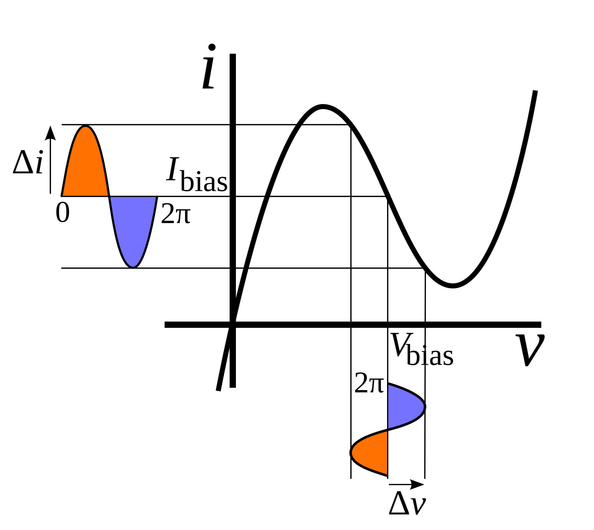
English: Current-voltage (IV) curve of a negative differential resistance device, showing how it can amplify an AC signal applied to it. The diagram shows a negative diff. resistance device biased into its negative resistance region with a DC bias voltage Vbias, and an AC voltage Δv applied to it, showing the current and voltage waveforms across it. In the negative resistance region an increase in voltage will cause a decrease in current, so Δi and Δv have opposite signs. Therefore the AC current and voltage waveforms across the device are 180° out of phase (indicated by the colored half-cycles). So the AC power dissipation in the device, the product of the AC voltage and current PAC = ΔiΔv is negative, it produces power that is consumed by the external circuit. Therefore with the proper external circuit it can increase the power of an applied signal, amplifying it. |
| Date | |
| Source | Own work |
| Author | Chetvorno |
Licensing edit
| This file is made available under the Creative Commons CC0 1.0 Universal Public Domain Dedication. | |
| The person who associated a work with this deed has dedicated the work to the public domain by waiving all of their rights to the work worldwide under copyright law, including all related and neighboring rights, to the extent allowed by law. You can copy, modify, distribute and perform the work, even for commercial purposes, all without asking permission.
|
File history
Click on a date/time to view the file as it appeared at that time.
| Date/Time | Thumbnail | Dimensions | User | Comment | |
|---|---|---|---|---|---|
| current | 18:57, 29 November 2013 | | 946 × 844 (18 KB) | Chetvorno (talk | contribs) | Increased saturation of colors and width of lines to improve clarity on some displays |
| 18:07, 5 June 2013 |  | 946 × 844 (18 KB) | Chetvorno (talk | contribs) | Changed style of guidelines | |
| 17:37, 5 June 2013 |  | 946 × 844 (18 KB) | Chetvorno (talk | contribs) | Increased weight of curve, changed axis labels to lower case, changed color and style of guidelines, added phase to current and voltage waveforms | |
| 07:53, 18 July 2012 |  | 954 × 884 (17 KB) | Chetvorno (talk | contribs) |
You cannot overwrite this file.
File usage on Commons
There are no pages that use this file.
File usage on other wikis
The following other wikis use this file:
- Usage on en.wikipedia.org
- Usage on ja.wikipedia.org