File:Berliner Poulsen arc ship radiotelephone-colorized.jpg

Size of this preview: 743 × 600 pixels. Other resolutions: 297 × 240 pixels | 595 × 480 pixels | 951 × 768 pixels | 1,268 × 1,024 pixels | 1,516 × 1,224 pixels.
Original file (1,516 × 1,224 pixels, file size: 402 KB, MIME type: image/jpeg)
Captions
Captions
Marine radiotelephone transceiver, 1919
Summary
edit
| Description |
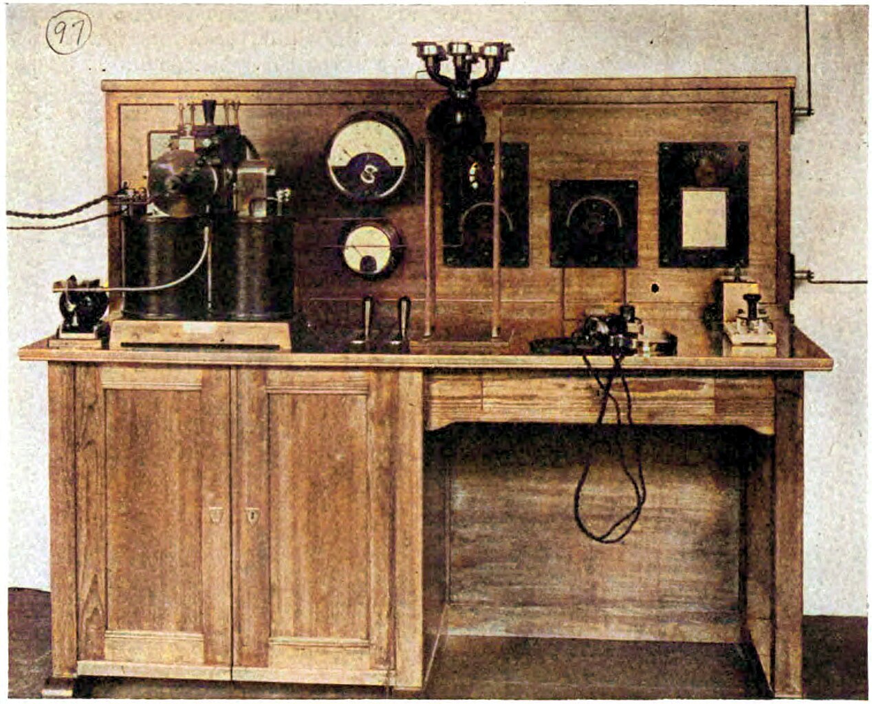
English: One of the first AM voice radiotelephone stations used on ships, 1919, made by the J. Berliner Co. of Vienna. It uses a 3 kW Poulsen arc radio transmitter (black mechanism, left), one of the first technologies capable of transmitting audio, used from 1903 until vacuum tubes replaced it in the mid-1920s. It consists of an electric arc between two electrodes in a chamber of alcohol vapor, between the poles of an electromagnet. A resonant circuit consisting of a coil and capacitor is connected across the electrodes. When a DC voltage is applied, the negative resistance of the arc generates oscillating radio frequency currents, which are applied to the antenna. The carbon microphone, (center top) is connected directly in the antenna wire and it's varying resistance modulates the RF current to the antenna. The microphone must handle the 3 kW (~3.5 amp) power output, so it is made of 6 microphones in series. The station can transmit either radiotelephony (sound) or radiotelegraphy (Morse code) at a higher output power; there is a telegraph key on the desk. The receiver uses a crystal detector. With a 45 meter (150 ft) mast antenna, it could transmit 50 to 100 km (30 to 50 miles). Français : Une des premières stations radiotéléphoniques vocales AM utilisées sur les navires, 1919, fabriquée par la J. Berliner Co. de Vienne. Il utilise un émetteur radio à arc Poulsen de 3 kW (mécanisme noir, à gauche), l'une des premières technologies capables de transmettre l'audio, utilisé à partir de 1903 jusqu'à ce que les tubes à vide le remplacent au milieu des années 1920. Il se compose d'un arc électrique entre deux électrodes dans une chambre de vapeur d'alcool, entre les pôles d'un électro-aimant. Un circuit résonnant composé d'une bobine et d'un condensateur est connecté aux bornes des électrodes. Lorsqu'une tension continue est appliquée, la résistance négative de l'arc génère des courants de radiofréquence oscillants, qui sont appliqués à l'antenne. Le microphone en carbone (au centre en haut) est connecté directement dans le fil de l'antenne et sa résistance variable module le courant RF vers l'antenne. Le microphone doit gérer la puissance de sortie de 3 kW (~ 3,5 ampères), il est donc composé de 6 microphones en série. La station peut transmettre soit la radiotéléphonie (son) ou la radiotélégraphie (code Morse) à une puissance de sortie plus élevée; il y a une clé télégraphique sur le bureau. Le récepteur utilise un détecteur à cristal. Avec une antenne à mât de 45 mètres, elle pourrait transmettre de 50 à 100 km (30 à 50 miles).
|
| Date | |
| Source | Downloaded 23 September 2013 from Alfred Norton Goldsmith (1918) Radio Telephony, The Wireless Press, Inc., New York, p. 32, fig. 21 on Google Books |
| Author | Alfred Norton Goldsmith + F1jmm |
| Other versions | Berliner Poulsen arc ship radiotelephone.jpg original black and white version |
Licensing
edit
This media file is in the public domain in the United States. This applies to U.S. works where the copyright has expired, often because its first publication occurred prior to January 1, 1929, and if not then due to lack of notice or renewal. See this page for further explanation.
|
 | |
 |
This image might not be in the public domain outside of the United States; this especially applies in the countries and areas that do not apply the rule of the shorter term for US works, such as Canada, Mainland China (not Hong Kong or Macao), Germany, Mexico, and Switzerland. The creator and year of publication are essential information and must be provided. See Wikipedia:Public domain and Wikipedia:Copyrights for more details.
|
| This is a retouched picture, which means that it has been digitally altered from its original version. Modifications: picture manager bright. Modifications made by F1jmm.
|
| Annotations | This image is annotated: View the annotations at Commons |
File history
Click on a date/time to view the file as it appeared at that time.
| Date/Time | Thumbnail | Dimensions | User | Comment | |
|---|---|---|---|---|---|
| current | 19:07, 4 October 2020 | | 1,516 × 1,224 (402 KB) | F1jmm (talk | contribs) | Uploaded own work with UploadWizard |
You cannot overwrite this file.
File usage on Commons
There are no pages that use this file.
File usage on other wikis
The following other wikis use this file:
- Usage on fr.wikipedia.org