File:Crystal radio receiver from wireless era.png
Original file (1,592 × 889 pixels, file size: 350 KB, MIME type: image/png)
Captions
Captions
Summary edit
| Description |
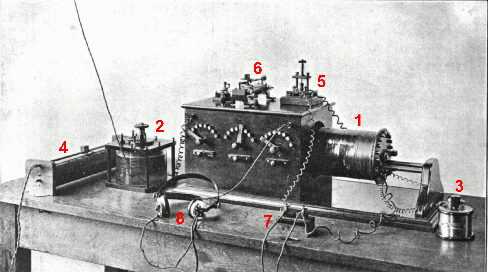
English: Early crystal radio receiver built by a radio amateur in Belfast, Ireland, during the pioneering wireless telegraphy era of radio around the first decade of the 20th century, showing examples of the early electronic components used. From a 1914 radio book. This example is a sophisticated inductively-coupled type, with an air-core antenna coupling transformer (called a loose coupler) to improve selectivity (Q factor) by adjusting the inductive coupling. This was used to receive long wave (148 - 283 kHz) radiotelegraphy broadcasts. Alterations to image: Added colored labels. The labelled parts are identified on p. 264 of the source text as:
(1) Adjustable antenna coupling transformer, called a "loose coupler". The secondary coil, visible on the right, slides in and out of the primary coil in the box, to adjust the coupling of the antenna to improve selectivity. The switches on the front of the box select taps on the coil to adjust the impedance match between the antenna and the receiver |
| Date | |
| Source | Downloaded 2009-11-14 from Rupert Stanley (1914) Textbook on Wireless Telegraphy, Vol. 1, Longmans Green & Co., New York, p.265, fig. 151 on Google Books |
| Author | Rupert Stanley |
| Permission (Reusing this file) |
Public domain in USA - published in USA prior to 1923 |
Licensing edit
This media file is in the public domain in the United States. This applies to U.S. works where the copyright has expired, often because its first publication occurred prior to January 1, 1929, and if not then due to lack of notice or renewal. See this page for further explanation.
|
 | |
 |
This image might not be in the public domain outside of the United States; this especially applies in the countries and areas that do not apply the rule of the shorter term for US works, such as Canada, Mainland China (not Hong Kong or Macao), Germany, Mexico, and Switzerland. The creator and year of publication are essential information and must be provided. See Wikipedia:Public domain and Wikipedia:Copyrights for more details.
|
| Annotations | This image is annotated: View the annotations at Commons |
File history
Click on a date/time to view the file as it appeared at that time.
| Date/Time | Thumbnail | Dimensions | User | Comment | |
|---|---|---|---|---|---|
| current | 10:15, 26 November 2009 | | 1,592 × 889 (350 KB) | Chetvorno (talk | contribs) | {{Information |Description={{en|Wikipedia:Crystal radio receiver from the wireless era.}} |Source=Downloaded 2009-11-14 from Rupert Stanley (1914) ''Textbook on Wireless Telegraphy, Vol. 1'', Longmans Green & Co., New York, p.265, fig. 151 on Goo |
You cannot overwrite this file.
File usage on Commons
The following page uses this file:
File usage on other wikis
The following other wikis use this file:
- Usage on ba.wikipedia.org
- Usage on de.wikipedia.org
- Usage on en.wikipedia.org
- Usage on es.wikipedia.org
- Usage on fr.wikipedia.org
- Usage on kk.wikipedia.org
- Usage on ru.wikipedia.org
- Usage on tg.wikipedia.org
- Usage on uz.wikipedia.org