File:Pulse Step Modulator simplified block diagram.svg

Original file (SVG file, nominally 980 × 780 pixels, file size: 35 KB)
Captions
Captions
Summary edit
| DescriptionPulse Step Modulator simplified block diagram.svg |
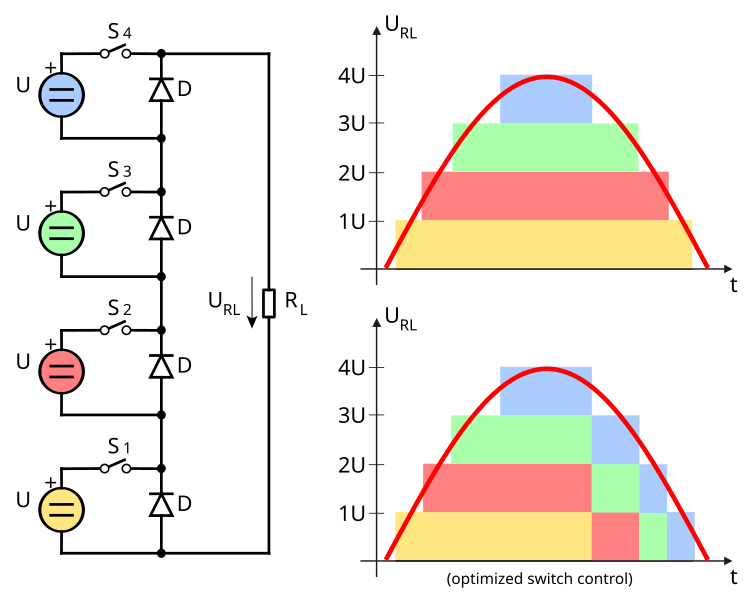
English: Simplified block diagram of a Pulse Step Modulator (PSM) used e.g. in high power AM modulators and short wave radio transmitters The PSM consist of N series-connected modules. In the block diagram only four modules in different colors shown, for simplicity. Typical PSM modulators consist of 32 up to 64 modules in series. Each module consisting of
The output voltage URl is equal on all modules. With switch S the voltage per module can be switched to the output or not. If switch S in a module is open, the diode D provides a current path for the output current of the other modules in series with a closed switch S. The output voltage URl can be controlled stepwise, shown on the right side in the colorized timing diagrams. In the optimized version (bottom on the right) with equal load on all modules the module with the longest on time (for example the yellow module) is switched off first. |
| Date | 7 June 2015 (upload date) |
| Source | Own work |
| Author | wdwd |
Licensing edit
- You are free:
- to share – to copy, distribute and transmit the work
- to remix – to adapt the work
- Under the following conditions:
- attribution – You must give appropriate credit, provide a link to the license, and indicate if changes were made. You may do so in any reasonable manner, but not in any way that suggests the licensor endorses you or your use.
- share alike – If you remix, transform, or build upon the material, you must distribute your contributions under the same or compatible license as the original.
File history
Click on a date/time to view the file as it appeared at that time.
| Date/Time | Thumbnail | Dimensions | User | Comment | |
|---|---|---|---|---|---|
| current | 16:40, 7 June 2015 |  | 980 × 780 (35 KB) | Wdwd (talk | contribs) | == {{int:filedesc}} == {{Information |Description={{en|Simplified block diagram of a ''Pulse Step Modulator'' (PSM) used e.g. in high power AM modulators and short wave radio transmitters<br/>The PSM consist of N series-connected modules. In the block... |
You cannot overwrite this file.
File usage on Commons
There are no pages that use this file.
File usage on other wikis
The following other wikis use this file:
- Usage on de.wikipedia.org
Metadata
This file contains additional information such as Exif metadata which may have been added by the digital camera, scanner, or software program used to create or digitize it. If the file has been modified from its original state, some details such as the timestamp may not fully reflect those of the original file. The timestamp is only as accurate as the clock in the camera, and it may be completely wrong.
| Width | 980 |
|---|---|
| Height | 780 |