File:Pulse relay.jpg

Pulse_relay.jpg(762 × 396 pixels, file size: 33 KB, MIME type: image/jpeg)

Captions

Captions

Add a one-line explanation of what this file represents

Summary edit

Description
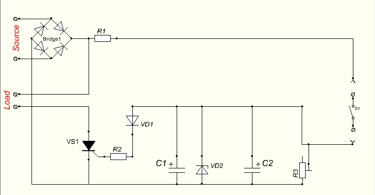
English: Principial wiring diagram of pulse relay.
  • Bridge rectifier and thyristor VS1 should be chosen due to the load
  • R1, R2 and VD1 should be chosen due to VS1 datasheet
  • C1 and R3 should be chosen due to load's worktime
  • VD2 should be 5.1V only; otherwise you'll burn thyristor's gate
  • C2 should be chosen due to thyristor's gate current
  • S1 should be designed for your voltage, but current 1A is enough
  • C1 could be replaced by programmable controller, but joinpoint between VD1, VD2, C1 should be removed and connected to controller's.
Way of working is very simple - you put switch S1 on, after current gains to C1. After you put switch off, capacitor C1 begin to discharge. While C1 is discharging, thyristor VS1 keeps load switched on mode. After end of C1 discharging, VS1 switchs off the load.
Date
Source Own work
Author Fully designed by Dmitry G
Permission
(Reusing this file)
I, the copyright holder of this work, hereby publish it under the following licenses:
w:en:Creative Commons
attribution share alike
This file is licensed under the Creative Commons Attribution-Share Alike 3.0 Unported license.
You are free:
  • to share – to copy, distribute and transmit the work
  • to remix – to adapt the work
Under the following conditions:
  • attribution – You must give appropriate credit, provide a link to the license, and indicate if changes were made. You may do so in any reasonable manner, but not in any way that suggests the licensor endorses you or your use.
  • share alike – If you remix, transform, or build upon the material, you must distribute your contributions under the same or compatible license as the original.
GNU head Permission is granted to copy, distribute and/or modify this document under the terms of the GNU Free Documentation License, Version 1.2 or any later version published by the Free Software Foundation; with no Invariant Sections, no Front-Cover Texts, and no Back-Cover Texts. A copy of the license is included in the section entitled GNU Free Documentation License.
You may select the license of your choice.

File history

Click on a date/time to view the file as it appeared at that time.

Date/TimeThumbnailDimensionsUserComment
current19:20, 16 May 2010Thumbnail for version as of 19:20, 16 May 2010762 × 396 (33 KB)Dmitry G (talk | contribs){{Information |Description={{en|1=Principial wiring diagram of pulse relay. *Bridge rectifier and thyristor VS1 should be chosen due to the load *R1, R2 and VD1 should be chosen due to VS1 datasheet *C1 and R3 should be chosen due to load's worktime *

The following 2 pages use this file:

Metadata