File:Stafford Air & Space Museum, Weatherford, OK, US (17).jpg

Original file (4,016 × 6,016 pixels, file size: 16.42 MB, MIME type: image/jpeg)
Captions
Captions
Summary edit
.jpg&action=edit§ion=1)
| Description |
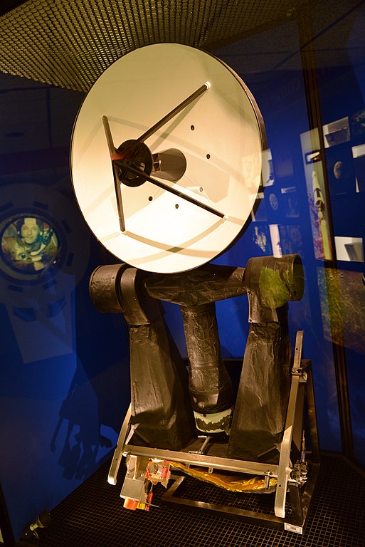
English: The rendezvous radar of an Apollo Lunar Module (LM). (Like all surviving LM hardware, this example never flew, since an LM, once launched, could not return to Earth.) The LM used this radar, located on top of its ascent stage, to track the Command/Service Module (CSM) when returning to it after leaving the lunar surface. The radar could be used either automatically, under the control of the LM's guidance computer and providing it with tracking data, or manually under the control of the crew, who would observe the CSM's tracking data on instruments. Thomas P. Stafford's Apollo 10 flight, which was a final rehearsal for the first Moon landing, brought the LM down to low altitude and then returned its ascent stage to the CSM, using the rendezvous radar to track it.
The rendezvous radar was a fully automatic continuous-wave Doppler radar that transmitted a continuous radio signal at a fixed carrier frequency of about 9.8 GHz (a wavelength of about 3.0 centimetres (1.2 in)). Unlike normal radars, the rendezvous radar did not detect its own reflected signal; instead, the transmitted signal was received by a transponder on the CSM and re-transmitted back to the LM at a frequency displaced by a fixed amount, while preserving the original signal's Doppler shift. The rendezvous radar received this re-transmitted "return signal", which was far stronger than a reflection of the original signal would have been, enabling the radar, with a radiative power of only 300 milliwatts, to track the CSM at ranges of up to 400 nautical miles (740 km; 460 mi). The return signal's frequency was displaced far enough from the original transmission's frequency that it could not possibly be confused with radar reflections, even Doppler-shifted ones, so the CSM transponder was the only object the radar could "see". The speed at which the CSM was approaching or receding could be found from the Doppler shift between the transmitted carrier frequency and that of the return signal (after adjusting for the known frequency displacement of the return signal). The radar transmission included a repeating sequence of low-frequency "range tones" phase-modulated on top of the carrier frequency. These tones were retained in the return signal, and by observing the round-trip times for the tones, the CSM's distance could be determined. The radar antenna had a Cassegrain configuration, with a parabolic reflector dish 24 inches (61 cm) in diameter, a smaller hyperbolic secondary reflector mounted in front of the dish, and the radar's feed horn antenna in the middle of the dish. Radar transmissions were beamed outward from the feed horn, where they would rebound off the secondary reflector to the dish, which would finally reflect them outward into space as a tightly confined beam. Return signals would follow this path in reverse to enter the feed horn, which had four ports arranged in a square. By comparing the signal strengths received in these ports (top vs. bottom, left vs. right), the radar could sense whether the return signal was coming in along the antenna's centerline or if it was displaced vertically or laterally, and by how much. The antenna had servomotors on its elevation and azimuth axes to orient it. Gyroscopes on each of these axes stabilized it, maintaining its direction in space even when the spacecraft as a whole rotated. When the radar was tracking the CSM, it would drive the antenna servomotors until the return signal had the same strength in all four ports of the feed horn, which would mean the antenna was pointing directly at the CSM. The radar could then sense the rotation angles of the two antenna axes and how fast they were changing as the CSM was being tracked. Combining all this information of distance, angles, and their rates of change gave the CSM's relative position and velocity. (As exhibited here, the antenna displayed is actually pointed "backwards", in the alternate orientation where the antenna was reversed and directed upward toward the CSM; this was used while the LM was sitting on the lunar surface or ascending towards orbit. In the normal orientation, during rendezvous in orbit, the antenna dish would point the other way, facing the same direction as the astronauts' view windows. The wrinkled black material on the antenna mount is a thermal covering also used on some other parts of the LM.) Displayed at the Stafford Air & Space Museum, Weatherford, Oklahoma, U.S. The museum was named for Stafford, a native of Weatherford. |
| Date | |
| Source | Own work |
| Author | Bubba73 |
Licensing edit
.jpg&action=edit§ion=2)
- You are free:
- to share – to copy, distribute and transmit the work
- to remix – to adapt the work
- Under the following conditions:
- attribution – You must give appropriate credit, provide a link to the license, and indicate if changes were made. You may do so in any reasonable manner, but not in any way that suggests the licensor endorses you or your use.
- share alike – If you remix, transform, or build upon the material, you must distribute your contributions under the same or compatible license as the original.
By Jud McCranie
File history
Click on a date/time to view the file as it appeared at that time.
| Date/Time | Thumbnail | Dimensions | User | Comment | |
|---|---|---|---|---|---|
| current | 02:06, 4 November 2018 | | 4,016 × 6,016 (16.42 MB) | SteinsplitterBot (talk | contribs) | Bot: Image rotated by 270° |
| 00:45, 4 November 2018 |  | 6,016 × 4,016 (16.66 MB) | Bubba73 (talk | contribs) | VicuñaUploader 1.23 |
You cannot overwrite this file.
File usage on Commons
The following 3 pages use this file:
.jpg&oldid=806166063)