Sameboat
+&*!. # The best legend for a map is without a legend.
|
About me edit
Sameboat - 同舟 (tung4 jau1)
- Nationality: Chinese
- Birth place: Hong Kong
- Current location: Yokohama
- Ethnicity: Han
- Birth year: 1983 (41)
- Native language: Cantonese
- Other handy languages: English, Mandarin, Japanese
- Languages I wanted to learn but have been postponed: Russian
- Occupation: Video game effect artist, indie asset developer/provider
- Letter from the author of TfL rail map (CC4) on Wikimedia
- File mover
Gallery edit
Hong Kong MTR edit
-
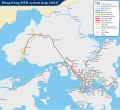 Geographically accurate, English (PDF)
 -
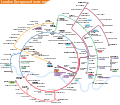
 Concentric ring pattern (PDF)
 -
 Shatin to Central Link
 -
 South Island Line and West Island Line
 -
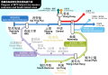
 North Island Line swap scheme, Traditional Chinese
 -
 North Island Line swap scheme, English
 -
 North Island Line interchange scheme, Traditional Chinese
 -
 North Island Line interchange scheme, English
 -
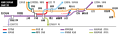
 Yau Tong and Tiu Keng Leng stations track diagram, simplified


Moscow Metro edit
- Because of my new career in a foreign country and the Moscow integral rail network has grown so enormously, I have to step down from updating all of my Moscow Metro maps except for minor revisions. (February 2020)
- Versions without future plans will no longer be maintained since the inclusion of Moscow Central Circle (Line 14) on 11th September 2016.
- Someone complaint that s/he was using this map to find the railway station for October Railway and ended up at Oktyabrskaya metro station instead of Komsomolskaya...
-
 English (Central Circle, future extensions and plans / PDF)
 -
 Russian (Central Circle, future extensions and plans / PDF)
 -
 German (PDF)
 -
 English (PDF)
 -
 Russian (PDF)
 -
 Russian (future extensions and plans / PDF)
 -
 Ukrainian (PDF)
 -
 Simplified Chinese (PDF)
 -
 Traditional Chinese (PDF)


St. Petersburg Metro edit
-
 English
 -
 Russian
 -
 Ukrainian
 -
 Simplified Chinese


United Kingdom edit
-
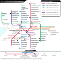
 Underground, Overground, DLR and Crossrail (PDF)
 -

-

-
 Bonus
Bonus -
 Overground English (PDF)
 -
 Overground Traditional Chinese (PDF)
 -
 Overground in concentric ring pattern (PDF)
 -
 West Coast Main Line


Misc. edit


Design principles of a good topological diagram for journey planning edit
Many of the rules outlined below are digested from Maxwell J. Roberts' researches, surveys and analyses, although he may not completely agree with all of my points. The rules can be deviated if it does not compromise legibility too much. Roberts' June 2017 newsletter demonstrates concise examples of what not to do in topological transit diagram compared to the optimal result.
Route path edit
"Path" is just the term used by SVG, it is the same as "outline" in Adobe Illustrator. Either way, it is the very "line" that connects station icons and represents the "track" in a rail map or "road" in a road map.
- Opt for straight vertical path above all else unless the targeting language permits vertical writing such as Chinese and Japanese.
- Reduce corners or bends as much as possible.
- Avoid hard corner and instead use rounded corner.
- Use circular arc instead of Bézier curve for rounded corner.
- The radius of the rounded corner should be consistent all through the map.
- However, if the paths are closely parallel to each other and they turn to the same direction, adjust the radius (greater for the “outer corner” and vice versa) so these arcs share the same centre.
- Angle of the diagonal paths (linearity) should be consistent all through.
- Choose a linearity which best fits the system shape.
- If the system shape is extremely irregular, choose a popular linearity: octolinearity (45°) or hexalinearity (30°/60°).
- If mixing different linearities is needed (e.g. 45° with 60°), each diagonal path should be parallel (or to lesser extent, perpendicular) to at least 1 another path or shape.
- Avoid bending greater than 90° which creates acute angle as much as possible.
- If such bend is inevitable, use greater radius of the arc.
- If the bend collides with other paths inevitably, place the more complicated bent path over the simpler path.
Only attempt these if the rules of the above are properly adhered:
- Bend the path for reducing the dimension of the map and wasted space.
- Bend the path for adhering to geographical reality.
- Arrange the sorting order of the paths for adhering to the elevation reality of the flying junction.
Basic SVG template for railway diagram edit
- Copy the following codes to any text editor. Save as .svg file and load it in any modern browser. Refresh the browser for an updated preview of the image each time you have made and saved any change in the text editor.
- Attribute "d" contains the path data in path element. In most cases I use absolute value (uppercase path command) for moveto (M, beginning of any new path), straight line (L), horizontal line (H) and vertical line (V); relative value (lowercase path command) for curves (a, q, c) because curve commands contain more parameters. The path data format (new line for any straight line command) I employ as seen in the template below is non-standard, but I think it's clearer for human understanding.
- Upload the SVG file to SVG Check for temporary PNG preview rendered by librsvg on Wikimedia.
- Upload the SVG file to W3 validator before uploading to Wikimedia or if SVG Check fails to render the file for more detailed XML error report.
- If you load the codes in Inkscape or other graphic editors, the transform values will most likely be transformed into ciphered/esoteric matrix values. It's a pain in the neck to decipher the matrix value manually.
- Watch my YouTube video for basic workflow of using this template.
<?xml version="1.0" encoding="UTF-8"?>
<svg
xmlns="http://www.w3.org/2000/svg"
xmlns:xlink="http://www.w3.org/1999/xlink"
width="300" height="200"
viewBox="0 0 300 200"
>
<title>Basic SVG template for railway diagram</title>
<style type="text/css">
<!--type="text/css" is required otherwise librsvg won't load anything from style element.-->
<!--Class name begins with a dot in the style element. It is recalled in other element with the "class" attribute.-->
text {font-family:Arimo,Liberation Sans,Arial,sans-serif}
.me {fill:none;stroke-width:5}
.spiccadilly {stroke:#0019A8}
</style>
<defs><!--stores object instances to be used for more than once with the "use" element.-->
<g id="term"><path class="me" d="M -7.5,0 H 7.5"/></g>
<g id="st"><path class="me" d="M -2,0 H 7.5"/></g>
<g id="termpiccadilly"><use xlink:href="#term" class="spiccadilly"/></g>
<g id="stpiccadilly"><use xlink:href="#st" class="spiccadilly"/></g>
<g id="int">
<circle cx="0" cy="0" r="8.25" fill="#fff"/>
<circle cx="0" cy="0" r="6" style="fill:#fff;stroke:#000;stroke-width:3"/>
</g>
</defs>
<rect id="background" x="-10" y="-10" width="500" height="500" fill="#eee"/>
<g id="Line_route" class="me">
<!--Never leave any space in id name and do not begin the id name with number; avoid punctuation and non-English characters too.-->
<!--You can add more class in the same class attribute. Separate the classes with a space.-->
<path id="Piccadilly_line_route" class="spiccadilly" d="
M 40,40
H 100 q 14,0 24,10
L 164,90 q 10,10 10,24
V 170
"/>
</g>
<g id="Piccadilly_line_station_icons">
<use xlink:href="#termpiccadilly" transform="translate(40,40)rotate(90)" id="Uxbridge"/>
<use xlink:href="#stpiccadilly" transform="translate(95,40)rotate(-90)" id="Sudbury_Town"/>
<use xlink:href="#int" x="134" y="60" id="Hammersmith"/>
<!--int icon is omnidirectional so no need for transform/rotate on diagonal line.-->
<use xlink:href="#stpiccadilly" transform="translate(164,90)rotate(135)" id="Knightsbridge"/>
<use xlink:href="#stpiccadilly" x="174" y="130" id="Russell_Square"/>
<use xlink:href="#termpiccadilly" x="174" y="170" id="Cockfosters"/>
</g>
<g id="text_labels" font-size="15px" transform="translate(0,5)">
<!--Unlike other attributes, value of font-size attribute should always include the unit (px) otherwise it may be interpreted differently.-->
<!--Translate value equalizes the height difference of text labels above and below the horizontal line.-->
<g text-anchor="middle">
<text x="40" y="58">Uxbridge</text>
<!--y of text below horizontal line = y of icon +18.-->
<text x="95" y="22">Sudbury Town</text>
<!--y of text above horizontal line = y of icon -18.-->
</g>
<text x="144" y="50">Hammersmith & City</text>
<!--x,y of text alongside diagonal line = x,y of icon ±10. Use & for &.-->
<text x="154" y="100" text-anchor="end">Knightsbridge</text>
<text x="186" y="124">Russell <tspan x="186" dy="13">Square</tspan></text>
<!--x of text on the right-hand side of vertical line = x of icon +12.-->
<!--Use tspan for broken label. Increase dy value for greater line height of text.-->
<!--Subtract y value of the text element by half of the dy value for vertically centred 2-line text.-->
<text x="162" y="170" text-anchor="end">Cockfosters</text>
<!--x of text on the left-hand side of vertical line = x of icon -12.-->
</g>
</svg>
Useful curves for SVG topological diagram edit
- The origin (0,0) is located at the upper-left corner of the image.
- Strictly speaking, the control points of my quadratic Bézier curves do not give the perfect circular arcs, they are simply the intersections of the 2 straight lines. Knowing the relative position of this intersection helps calculating the destination of the entry straight line before the curve kicks in, even if you're using the equivalent elliptical arc command.
- In this tutorial, zero degree (0°) is pointing to right/east as per the left-to-right writing convention.
- The letter case of the path commands (L, Q, A, etc.) in the path data is case-sensitive. Uppercase denotes absolute position of the following value(s); lowercase denotes relative position to the last absolute value.
- The comma (,) between x and y coordinates and flag values can be replaced by white-space. I just feel using the comma is clearer.
- You can hard return within the path data as you please.
- SVG rotation property accepts negative angle degree value and degree value greater than 360 (e.g. -45 or 730). Not really related to this topic, jfyi.
- Most values in this tutorial are rounded for ease of remembering and calculating. They are not meant to be absolutely accurate. But the inaccuracy is very unnoticeable to the naked eye.
- If you are editing the curve with Inkscape's curve tools, it will always convert your modified curve to cubic Bézier curve (C) and revert the shorthanded cubic Bézier curve command (S) back to non-shorthanded command.
- When making concentric curves closely juxtapose to each other, use the same curve command (preferably elliptical arc). Mixing 2 different curve commands will result in undesirable gap between the curves.
45° edit

Green curve: q 10,10 24,10
| Angle from/to | Path data | Mid. position | Mid. rotation | ||
|---|---|---|---|---|---|
| Cardinal direction to ordinal direction | |||||
| 0° to 45° | →↘ | q 14,0 24,10 |
(13,2.6) | 22.5° | |
a 34,34 0 0,1 24,10
| |||||
c 10,0 17,3 24,10
| |||||
c 9,0 17.6,3.6 24,10
| |||||
| 0° to -45°/315° | →↗ | q 14,0 24,-10 |
(13,-2.6) | -22.5°/337.5° | |
| 90° to 135° | ↓↙ | q 0,14 -10,24 |
(-2.6,13) | 112.5° | |
| 90° to 45° | ↓↘ | q 0,14 10,24 |
(2.6,13) | 67.5° | |
| 180° to -135°/225° | ←↖ | q -14,0 -24,-10 |
(-13,-2.6) | -157.5°/202.5° | |
| 180° to 135° | ←↙ | q -14,0 -24,10 |
(-13,2.6) | 157.5° | |
| -90/270° to -45°/315° | ↑↗ | q 0,-14 10,-24 |
(2.6,-13) | -67.5°/292.5° | |
| -90/270° to -135°/225° | ↑↖ | q 0,-14 -10,-24 |
(-2.5,-12.9) | -112.5°/247.5° | |
| Ordinal direction to cardinal direction | |||||
| 45° to 90° | ↘↓ | q 10,10 10,24 |
(7.4,11) | 67.5° | |
| 45° to 0° | ↘→ | q 10,10 24,10 |
(11,7.4) | 22.5° | |
| 135° to 180° | ↙← | q -10,10 -24,10 |
(-11,7.4) | 157.5° | |
| 135° to 90° | ↙↓ | q -10,10 -10,24 |
(-7.4,11) | 112.5° | |
| -45°/315° to 0° | ↗→ | q 10,-10 24,-10 |
(11,-7.4) | -22.5°/337.5° | |
| -45°/315° to -90°/270° | ↗↑ | q 10,-10 10,-24 |
(7.4,-11) | -67.5°/292.5° | |
| -135°/225° to -90°/270° | ↖↑ | q -10,-10 -10,-24 |
(-7.4,-11) | -112.5°/247.5° | |
| -135°/225° to 180° | ↖← | q -10,-10 -24,-10 |
(-11,-7.4) | -157.5°/202.5° | |
- The coordinates of the control point and destination are found with simple Pythagorean theorem. The x of the control point in the 1st example should be accurately:
√2(102) = 14.142

- If using elliptical arc command (A/a) to draw the circular arc, when the coordinates of the destination, x and y, are given, the angle (θ) and radius (r) of the circular arc can be calculated with the following formulas:
- If x < y, θ will be an acute angle (conversely shorter and softer arc), otherwise obtuse:
- θ = 2 arctan(x/y)
- If x < y, θ will be an acute angle (conversely shorter and softer arc), otherwise obtuse:
r = √x2 + y2 or √x2 + y2 2 sin(θ/2) 2 sin[arctan(shorter side/longer side)]
- In our 1st example:
θ = 2 arctan(10/24.142) = 45.0002
| r = | √24.1422 + 102 | = 34.142 ≈ 34 |
| 2 sin(45/2) |
- Since the angle of the circular arc is 45°, the radius is as simple as the sum of x and y of destination (34=24+10).
- Therefore the relations of radius r, x and y in a 45° circular arc can be simplified as:
r = y × 3.4142 or x × 1.4142
x = y × 2.4142 or r / 1.4142
y = x / 2.4142 or r / 3.4142
Concentric 45° arc edit
| Angle from/to | Path data | Relative | ||
|---|---|---|---|---|
| r-30 | →↘ | a 4,4 0 0,1 2.8,1.2 |
x±7,y±3 | |
| r-20 | a 14,14 0 0,1 10,4
| |||
| r-10 | a 24,24 0 0,1 17,7
| |||
| r | a 34,34 0 0,1 24,10
| |||
| r+10 | a 44,44 0 0,1 31,13
| |||
| r+20 | a 54,54 0 0,1 38,16
| |||
| r+30 | a 64,64 0 0,1 45,19
| |||
90° edit
SVG elliptical arc (A/a) requires 7 values correctly given to all its parameters. The 1st, 2nd, 4th and 5th parameters are particularly susceptible to any invalid value and may cause the path or the whole SVG unable to be rendered.
- The first two values are x and y radii respectively. The arc will be drawn from the imaginary circle (identical x and y radii) or ellipse defined by these parameters. Negative value will invalidate the path because they are not position parameters but length parameters.
- The 3rd value is the degree of x-axis-rotation. This value is only meaningful when the first two values, x and y radii differ with each other which would create an ellipse rather than a perfect circle. But it will affect the offset of the stroke dash (behavior varies depending on which rendering software you are using).
- The 4th and 5th values are large-arc-flag and sweep-flag respectively. These 2 parameters only accept 0 (zero) or 1 to decide which kind/side of the arc should be drawn out of 4 possibilities.
- Large-arc-flag (4th parameter) determines if the outer larger arc (1) of the circle/ellipse should be drawn instead of the inner smaller arc (0). Normally for joining other parts of the path smoothly, only 0 value is used.
- Sweep-flag (5th parameter) determines which side of the arc should be drawn, depending on its direction. Value 1 draws the arc clockwise; value 0 draws the arc counter-clockwise.
- Same as other curve command parameters, the last 2 parameters (6th and 7th) are the destination position of the curve. The letter case of A/a only affects the absolute or relative positions of these 2 parameters here.

Green arc: a 30,30 0 0,1 -30,30
| Angle from/to | Path data | Mid. position | Mid. rotation | ||
|---|---|---|---|---|---|
| Cardinal direction to cardinal direction | |||||
| 0° to 90° | →↘↓ | a 30,30 0 0,1 30,30 |
(21.2,8.8) | 45° | |
c 16.5,0 30,13.5 30,30
| |||||
q 27,3 30,30
| |||||
| 0° to -90°/270° | →↗↑ | a 30,30 0 0,0 30,-30 |
(21.2,-8.8) | -45°/315° | |
| 90° to 180° | ↓↙← | a 30,30 0 0,1 -30,30 |
(-8.8,21.2) | 135° | |
| 90° to 0° | ↓↘→ | a 30,30 0 0,0 30,30 |
(8.8,21.2) | 45° | |
| 180° to -90°/270° | ←↖↑ | a 30,30 0 0,1 -30,-30 |
(-8.8,-21.2) | -135°/225° | |
| 180° to 90° | ←↙↓ | a 30,30 0 0,0 -30,30 |
(-21.2,8.8) | 135° | |
| -90°/270° to 0° | ↑↗→ | a 30,30 0 0,1 30,-30 |
(8.8,-21.2) | -45°/315° | |
| -90°/270° to 180° | ↑↖← | a 30,30 0 0,0 -30,-30 |
(-8.8,-21.2) | -135°/225° | |
| Ordinal direction to ordinal direction | |||||
| 45° to 135° | ↘↓↙ | a 21.2,21.2 0 0,1 0,30 |
(6.2,15) | 90° | |
a 30,30 0 0,1 0,42.4 |
(8.8,21.2) | ||||
| 45° to -45°/315° | ↘→↗ | a 21.2,21.2 0 0,0 30,0 |
(15,6.2) | 0° | |
| 135° to -135°/225° | ↙←↖ | a 21.2,21.2 0 0,1 -30,0 |
(-15,6.2) | 180° | |
| 135° to 45° | ↙↓↘ | a 21.2,21.2 0 0,0 0,30 |
(-6.2,15) | 90° | |
| -135°/225° to -45°/315° | ↖↑↗ | a 21.2,21.2 0 0,1 0,-30 |
(-6.2,-15) | -90°/270° | |
| -135°/225° to 135° | ↖←↙ | a 21.2,21.2 0 0,0 -30,0 |
(-15,-6.2) | 180° | |
| -45°/315° to 45° | ↗→↘ | a 21.2,21.2 0 0,1 30,0 |
(15,-6.2) | 0° | |
| -45°/315° to -135°/225° | ↗↑↖ | a 21.2,21.2 0 0,0 0,-30 |
(6.2,-15) | -90°/270° | |
- Radius r and destination x or y of a 90° ordinal direction to ordinal direction circular arc is a very straightforward Pythagorean relation:
r = √x2 / 2
x = √r2 × 2
Parallel shift edit

| Angle from/to | Path data | Mid. position | ||
|---|---|---|---|---|
| Cardinal direction shift | ||||
| 0° to 45° to 0° | →↘→ | c 10,0 10,10 20,10 |
(10,5) | |
q 5,0 10,5 t 10,5
| ||||
| 0° to -45° to 0° | →↗→ | c 10,0 10,-10 20,-10 |
(10,-5) | |
| 90° to 135° to 90° | ↓↙↓ | c 0,10 -10,10 -10,20 |
(-5,10) | |
| 90° to 45° to 90° | ↓↘↓ | c 0,10 10,10 10,20 |
(5,10) | |
| 180° to 225° to 180° | ←↖← | c -10,0 -10,-10 -20,-10 |
(-10,-5) | |
| 180° to 135° to 180° | ←↙← | c -10,0 -10,10 -20,10 |
(-10,5) | |
| -90° to -45° to -90° | ↑↗↑ | c 0,-10 10,-10 10,-20 |
(5,-10) | |
| -90° to 225° to -90° | ↑↖↑ | c 0,-10 -10,-10 -10,-20 |
(-5,-10) | |
| Ordinal direction shift | ||||
| 45° to 90° to 45° | ↘↓↘ | c 8,8 2,12 10,20 |
(5,10) | |
q 4,4 5,10 t 5,10
| ||||
| 45° to 0° to 45° | ↘→↘ | c 8,8 12,2 20,10 |
(10,5) | |
| 135° to 180° to 135° | ↙←↙ | c -8,8 -12,2 -20,10 |
(-10,5) | |
| 135° to 90° to 135° | ↙↓↙ | c -8,8 -2,12 -10,20 |
(-5,10) | |
| 225° to -90° to 225° | ↖↑↖ | c -8,-8 -2,-12 -10,-20 |
(-5,-10) | |
| 225° to 180° to 225° | ↖←↖ | c -8,-8 -12,-2 -20,-10 |
(-10,-5) | |
| -45° to 0° to -45° | ↗→↗ | c 8,-8 12,-2 20,-10 |
(10,-5) | |
| -45° to -90° to -45° | ↗↑↗ | c 8,-8 12,-2 20,-10 |
(5,-10) | |
135° edit
| Cardinal direction to ordinal direction | |||||
|---|---|---|---|---|---|
| Angle from/to | Path data | +90° position | +90° rotation | ||
| 0° to 135° CW | →↘↓↙ | a 20,20 0 0,1 14,34 |
(20,20) | 90° | |
| 0° to -135° CCW | →↗↑↖ | a 20,20 0 0,0 14,-34 |
(20,-20) | -90° | |
| 90° to 225° CW | ↓↙←↖ | a 20,20 0 0,1 -34,14 |
(-20,20) | 180° | |
| 90° to -45° CCW | ↓↘→↗ | a 20,20 0 0,0 34,14 |
(20,20) | 0° | |
| 180° to 315° CW | ←↖↑↗ | a 20,20 0 0,1 -14,-34 |
(-20,-20) | 270° | |
| 180° to 45° CCW | ←↙↓↘ | a 20,20 0 0,0 -14,34 |
(-20,20) | 90° | |
| -90° to 45° CW | ↑↗→↘ | a 20,20 0 0,1 34,-14 |
(20,-20) | 0° | |
| -90° to 135° CCW | ↑↖←↙ | a 20,20 0 0,0 -34,-14 |
(-20,-20) | 180° | |
| Ordinal direction to cardinal direction | |||||
| Angle from/to | Path data | +45° position | +45° rotation | ||
| 45° to 180° CW | ↘↓↙← | a 20,20 0 0,1 -14,34 |
(6,14) | 90° | |
| 45° to -90° CCW | ↘→↗↑ | a 20,20 0 0,0 34,-14 |
(14,6) | 0° | |
| 135° to 180° CW | ↙←↖↑ | a 20,20 0 0,1 -34,-14 |
(-14,6) | 180° | |
| 135° to -90° CCW | ↙↓↘→ | a 20,20 0 0,0 14,34 |
(-6,14) | 90° | |
| 225° to 180° CW | ↖↑↗→ | a 20,20 0 0,1 14,-34 |
(-6,-14) | -90° | |
| 225° to -90° CCW | ↖←↙↓ | a 20,20 0 0,0 -34,14 |
(-14,-6) | 180° | |
| -45° to 180° CW | ↗→↘↓ | a 20,20 0 0,1 34,14 |
(14,-6) | 0° | |
| -45° to -90° CCW | ↗↑↖← | a 20,20 0 0,0 -14,-34 |
(6,-14) | -90° | |
- Plus 0.142 to the coordinates of the destinations if you must be accurate.
26.565° edit
Because tan 26.565° = 0.5, meaning x:y = 2:1 on the straight slope.
| Angle from/to (θ) | Path data | Control point of Q | Radius (r) | Curve destination | ||||
|---|---|---|---|---|---|---|---|---|
| Cardinal direction to diagonal direction | ||||||||
| 0° to 26.565° | →↘ | a 38,38 0 0,1 17,4 |
|
(n√5 + 2),n) | ||||
q 9,0 17,4 |
(n√5,0) | |||||||
| 0° to -26.565° | →↗ | q 9,0 17,-4
| ||||||
| 90° to (90°-63.435°) | ↓↘ | a 22,22 0 0,0 12,20 |
√(n/2)2 + n2 | (r - n/2,n) | ||||
q 0,14 12,20 |
(0,r × tan(θ/2)) | |||||||
| 90° to (90°+63.435°) | ↓↙ | q 0,14 -12,20
| ||||||
| Diagonal direction to cardinal direction | ||||||||
| 26.565° to 0° | ↘→ | q 8,4 17,4
| ||||||
a 38,38 0 0,0 17,4
| ||||||||
| 26.565° to 90° | ↘↓ | q 12,6 12,20
| ||||||
a 22,22 0 0,1 12,20
| ||||||||
3:4:5 Pythagorean triple edit
- See my London TfL rail service diagram for actual usage.
32 + 42 = 52
arctan(3/4) = 36.8698976°
90 - 36.8698976 = 53.1301024
36.87° edit
| Angle from/to (θ) | Path data | Control point of Q | Radius (r) | Curve destination | ||
|---|---|---|---|---|---|---|
| Cardinal direction to diagonal direction | ||||||
| 0° to 37° | →↘ | q 15,0 27,9 |
(5n,0) | (9n,3n) / (3n,n) | ||
a 45,45 0 0,1 27,9 |
15n / 5n | |||||
q 13.33,0 24,8
| ||||||
a 40,40 0 0,1 24,8
| ||||||
| 90° to 37° | ↓↘ | q 0,20 16,32 |
(0,5n) | (4n,8n) / (2n,4n) | ||
a 40,40 0 0,0 16,32 |
10n / 5n | |||||
| 0° to (90°+53°) | →↘↓↙ | a 50,50 0 0,1 30,90 |
5n | (3n,9n) | ||
a 40,40 0 0,1 24,72
| ||||||
| 90° to -37° | ↓↘→↗ | a 50,50 0 0,0 80,40 |
(8n,4n) | |||
a 40,40 0 0,0 64,32
| ||||||
| Diagonal direction to cardinal direction | ||||||
| 37° to 0° | ↘→ | q 12,9 27,9 |
(4n,3n) | (9n,3n) / (3n,n) | ||
a 45,45 0 0,0 27,9 |
15n / 5n | |||||
q 10.67,9 24,8
| ||||||
a 40,40 0 0,0 24,8
| ||||||
| 37° to 90° | ↘↓ | q 16,12 16,32 |
(4n,3n) | (4n,8n) / (2n,4n) | ||
a 40,40 0 0,1 16,32 |
10n / 5n | |||||
| 37° to -90° | ↘→↗↑ | a 50,50 0 0,0 80,-40 |
5n | (8n,-4n) | ||
a 40,40 0 0,0 64,-32
| ||||||
| 37° to 180° | ↘↓↙← | a 50,50 0 0,1 -30,90 |
(-3n,9n) | |||
a 40,40 0 0,1 -24,72
| ||||||
| Diagonal direction to diagonal direction | ||||||
| 37° to -37° | ↘→↗ | a 40,40 0 0,0 48,0 |
5n | (6n,0) | ||
| 37° to (90°+53°) | ↘↓↙ | a 40,40 0 0,1 0,64 |
(0,8n) | |||
| U-turn | ||||||
| 37° to (180°+37°) | ↘↓↙←↖ | a 40,40 0 0,1 -48,64 |
5n | (-6n,8n) | ||
| 37° to (-90°-53°) | ↘→↗↑↖ | a 40,40 0 0,0 48,-64 |
5n | (6n,-8n) | ||
| Great loop | ||||||
| 0° to (180°+37°) | →↘↓↙←↖ | a 40,40 0 1,1 -24,72 |
5n | (-3n,9n) | ||
| 37° to 180° | ↘→↗↑↖← | a 40,40 0 1,0 24,-72 |
(3n,-9n) | |||
53.13° edit
| Angle from/to (θ) | Path data | Control point of Q | Radius (r) | Curve destination | ||
|---|---|---|---|---|---|---|
| Cardinal direction to diagonal direction | ||||||
| 0° to 53° | →↘ | q 20,0 32,16 |
(5n,0) | (8n,4n) / (4n,2n) | ||
a 40,40 0 0,1 32,16 |
10n / 5n | |||||
| 90° to 53° | ↓↘ | q 0,15 9,27 |
(0,5n) | (3n,9n) / (n,3n) | ||
a 45,45 0 0,0 9,27 |
15n / 5n | |||||
q 0,13.33 8,24
| ||||||
a 40,40 0 0,0 8,24
| ||||||
| 0° to (90°+37°) | →↘↓↙ | a 50,50 0 0,1 40,80 |
5n | (4n,8n) | ||
a 40,40 0 0,1 32,64
| ||||||
| 90° to -53° | ↓↘→↗ | a 50,50 0 0,0 90,30 |
(9n,3n) | |||
a 40,40 0 0,0 72,24
| ||||||
| Diagonal direction to cardinal direction | ||||||
| 53° to 0° | ↘→ | q 12,16 32,16 |
(3n,4n) | (8n,4n) / (4n,2n) | ||
a 40,40 0 0,0 32,16 |
10n / 5n | |||||
| 53° to 90° | ↘↓ | q 9,12 9,27 |
(3n,4n) | (3n,9n) / (n,3n) | ||
a 45,45 0 0,1 9,27 |
15n / 5n | |||||
q 8,10.67 8,24
| ||||||
a 40,40 0 0,1 8,24
| ||||||
| 53° to -90° | ↘→↗↑ | a 50,50 0 0,0 90,-30 |
5n | (9n,-3n) | ||
a 40,40 0 0,0 72,-24
| ||||||
| 53° to 180° | ↘↓↙← | a 50,50 0 0,1 -40,80 |
(-4n,8n) | |||
a 40,40 0 0,1 -32,64
| ||||||
| Diagonal direction to diagonal direction | ||||||
| 53° to -53° | ↘→↗ | a 40,40 0 0,0 64,0 |
5n | (8n,0) | ||
| 53° to (90°+37°) | ↘↓↙ | a 40,40 0 0,1 0,48 |
(0,6n) | |||
| U-turn | ||||||
| 53° to (180°+53°) | ↘↓↙←↖ | a 40,40 0 0,1 -64,48 |
5n | (-8n,6n) | ||
| 53° to (-90°-37°) | ↘→↗↑↖ | a 40,40 0 0,0 64,-48 |
5n | (8n,-6n) | ||
37° to/from 53° edit
| Angle from/to (θ) | Path data | Radius (r) | Curve destination | ||
|---|---|---|---|---|---|
| 37° to (90°+37°) | ↘↓↙ | a 40,40 0 0,1 8,56 |
5n | (n,7n) | |
| 53° to (90°+53°) | a 40,40 0 0,1 -8,56 |
(-n,7n) | |||
| 37° to -53° | ↘→↗ | a 40,40 0 0,0 56,-8 |
(7n,-n) | ||
| 53° to -37° | a 40,40 0 0,0 56,8 |
(7n,n) | |||
Changing curve radius without messing with the entry and exit paths edit
If you end up with more irrational numbers or repeating decimals in the resultant path data, it may be better to redo the path from scratch...
Example 1 edit
Original path data of a 37° clockwise kink from a horizontal path:
M 0,0 H 100 a 40,40 0 0,1 24,8 L 164,38
- Find out the intersection (control point of quadratic Bézier curve) of the entry and exit paths before the curve kinks in:
- ∵ Radius : xcontrol point = 15 : 5 = 3 : 1
- ∴ xcontrol point = Radius / 3 = 40 / 3 = 13.3
- Multiply the curve radius, curve destination and control point:
- Radius = 40 * 1.5 = 60
- Curve destination = (24,8) * 1.5 = (36,12)
- xcontrol point = 13.3 * 1.5 = 20
- Calculate the new entry coordinate(s) of the curve:
- 100 + 13.3 - 20 = 93.3 ≈ 93.33
New path data:
M 0,0 H 93.33 a 60,60 0 0,1 36,12 L 164,38
Path stroke with parallel stripe pattern edit
<defs>
<path id="path" fill="none" d="M 50,50 h 100 a 150,150 0 0,1 150,150 a 50,50 0 1,0 50,-50"/>
</defs>
<use xlink:href="#path" style="stroke:white;stroke-width:28"/>
<use xlink:href="#path" style="stroke:#444;stroke-width:23"/>
<use xlink:href="#path" style="stroke:white;stroke-width:18"/>
<use xlink:href="#path" style="stroke:#444;stroke-width:13"/>
<use xlink:href="#path" style="stroke:white;stroke-width:8"/>
<use xlink:href="#path" style="stroke:#444;stroke-width:3"/>
Aligning object on circular path edit
When aligning object alongside a perfectly circular path, the transform property is useful to eliminate guesswork by eye. Note that this method does not work on elliptical path. The procedure is to position the object to the center of the circle, then rotate the object to the desirable angle, finally "shoot" the object to the circumference by the radius of the circle:
<use xlink:href="#whatever" transform="translate(250,250)rotate(110)translate(50)"/>
The order of all translate and rotate values is not arbitrary and must be followed exactly for this alignment to work.
So in this case, the center of the circle is at (250,250), the radius is 50 px wide and the object is at 110° from east clockwise (the launching translation is applied on x-axis only because there is only 1 value for "translate", this makes 0° east). However, if your object is not omnidirectional and you want it to face a specific direction at its final position, there are 2 workarounds to achieve that. (a) You can add one last rotation at the end of the transform property, e.g. 20°:
<use xlink:href="#whatever" transform="translate(250,250)rotate(110)translate(50)rotate(20)"/>
If you only want to rotate the object back to its original direction, use the negative value of the first rotation:
<use xlink:href="#whatever" transform="translate(250,250)rotate(110)translate(50)rotate(-110)"/>
or (b) if you just want the object to turn 180°, change the initial rotation ±180° and the second translate of x, the radius, from positive value to negative, or vice versa:
<use xlink:href="#whatever" transform="translate(250,250)rotate(290)translate(-50)"/>
You can of course group the objects if they share the same center of the circular path or even the first rotation if they are at the same direction. Use the g element wisely to reduce the code size:
<g transform="translate(250,250)">
	<use xlink:href="#whatever" transform="rotate(110)translate(50,0)"/>
	<g transform="rotate(50)">
		<use xlink:href="#whatever" transform="translate(50)"/>
		<use xlink:href="#whatever" transform="translate(55)rotate(-50)"/>
		<use xlink:href="#whatever" transform="translate(60)rotate(20)"/>
	</g>
	<use xlink:href="#whatever" transform="rotate(290)translate(-50)"/>
</g>
Absolute position after transformation:
x = xcentre + radius × cos θ
y = ycentre + radius × sin θ
- Applicable if 0° is pointing to east. If 0° is north then x will be calculated with sine and y with cosine. In such case, the "launching translate" should be written as, e.g.
translate(0,-50)instead oftranslate(50).
45°-diagonal-line-circle intersection edit
- Obtain a point on the 45°-diagonal-line which shares the same height (y coordinate) of the circle's centre.
- Calculate the distance d between this point and the centre by subtraction of their x coordinates.
- Obtain either applicable value of x from this quadratic equation: 2x2 + 2xd + d2 - r2 = 0
- This is altered from the Pythagorean equation: x2 + (x + d)2 = r2
- θ = arccos (x / r)
- xintersection = xcentre + x
- yintersection = ycentre + x + d
Circle-circle intersection edit

When making my Washington Metro diagram, I needed to find out the position of "Metro Center" station which lies on the intersection of 2 circular arcs of different radii. Wolfram MathWorld offers straightforward formulas which does not involve quadratic equation (there are online scripts to deal with that but still). So here are the basic data:
| Centre | Radius | |
|---|---|---|
| Smaller arc (Silver Line) | (0,0) | 70 |
| Larger arc (Red Line) | (160,-170) | 180 |
First I need to find out d, the distance between the 2 centres:
- d2 = 1602 + 1702
- d = √54500
The formula on line (5) in Wolfram MathWorld is all I need by now:
- x = (54500 - 702 + 1802) / 2√54500
- x = 175.6247
x belongs to the bigger arc. Along with the radius of the bigger arc, I can find out the angle α:
- α = arccos(175.6247 / 180)
- α = 12.658689
We are not done yet, this α is used to subtract the angle Α of the right triangle formed by joining the 2 centres of the arcs.
- Α = arctan(160 / 170) or arccos(170 / √54500) you must be crazy to calculate it using cosine!
- Α = 43.2642954
So the actual angle of the lower intersection from the direction of south (augmenting y-coordinate, in the world of SVG) is:
- 43.2642954 - 12.658689 = 30.6056
As per the convention detailed in the previous section, south equals to 90°, so the resultant angle of the lower intersection from 0°:
- 90 + 30.6056 = 120.6056
This is what I write in the actual SVG:
<use xlink:href="#int" transform="translate(160,-170)rotate(120.6056)translate(180)"><title>Metro Center</title></use><!--Absolute x="68.3574" y="-15.075"-->
I also calculated the absolute position for locating the text label using my formulas in the previous section.
Circular arc bends to its normal smoothly edit
As far as I know, Inkscape does not support snapping the edge of circle to the intersections of normal and tangent of 2 objects (either circle, curve and straight line.)
- If the arc bends to the exterior of the arc:

- If the arc bends to the interior of the arc, "(θ + 90) / 2" in the formulas becomes "(90 - θ) / 2"
| Exterior | Interior | ||||||
|---|---|---|---|---|---|---|---|
| sin θ = | r2e | sin θ = | r2i | ||||
| r1 + r2e | r1 - r2i | ||||||
| r2e = | sin θ × r1 | r2i = | sin θ × r1 | ||||
| 1 - sin θ | 1 + sin θ | ||||||
(This seems more cumbersome than calculating by tangent...)
Bends to parallel to the normal edit
- p = parallel distance between the normals
- α = pointing angle of the normal of the entrance curve, assuming the entry angle of the curve is turning clockwise (regardless of the direction during the bend to normal).
| Exterior | Interior | |
|---|---|---|
| Closer | r2ep = (tan θ × r1 - p / cos θ) × tan[(θ + 90) / 2] | r2ip = (tan θ × r1 - p / cos θ) × tan[(90 - θ) / 2] |
| Farther | r2ep = (tan θ × r1 + p / cos θ) × tan[(θ + 90) / 2] | r2ip = (tan θ × r1 + p / cos θ) × tan[(90 - θ) / 2] |
| centrer2ep = (xcentre + cos α × (r + r2ep), ycentre + sin α × (r + r2ep)) destination = (xcentre r2ep + cos(α + θ + 90) × r2ep, ycentre r2ep + sin(α + θ + 90) × r2ep) |
centrer2ip = (xcentre + cos α × (r - r2ip), ycentre + sin α × (r - r2ip)) destination = (xcentre r2ip + cos(α + θ + 90) × r2ip, ycentre r2ip + sin(α + θ + 90) × r2ip) |
Interior tangents between different circles edit

- diameterm = rm × 2
- dm = √height difference between 2 centres2 + width difference between 2 centres2
x = (r1 + r2)2 dm
tan β = height difference between 2 centres width difference between 2 centres
cos(α + β) = x r1 + r2
- Use angle α to calculate the exit and entry points of the arcs for joining the tangent.
SVG animation edit
- General
- Firefox: Most compatible/forgiving. Accepts curve by elliptical arc command. The other 2 browsers only accept cubic Bézier curve command.
- Chrome: Stricter format of animation "value". Excessive space or new line may disable the animation.
- Safari: Animation of elliptical arc command is not allowed.
- IE: What is that? Something edible?
- Multiple usages of the same animated object
- Firefox: Each usage is treated independently from other usage.
- Chrome: All usages share the same "begin" and "end" trigger.
Incorporating interactive functions in SVG without script edit
Despite Google's decision to discontinue maintenance of SMIL component in Chrome, one of which powers the animation and interactive functionalities of SVG, I still want to spread it because SVG isn't just a cross-platform container for vector graphic. Wikimedia bans SVG with script due to security concern, so SMIL is the only* choice of creating animated/interactive SVG for Wikimedia, which is fine for me because I don't know scripting and I have other meaningful things occupying my life. SMIL is entirely XML-based, if you know how to code HTML, then you should have minimal troubles to understand SMIL.
* Actually CSS pseudo-classes like :hover can be used as well but it can only handles simple style change of the object which directly loads the said style class, and of course no real animation of a defined duration.
Although having said that, because SVG on Wikimedia must be first rendered into PNG raster format before being embedded into any wiki page, that means the SVG in the wiki page is not animated/interactive. Any animated/interactive SVG must be opened separately in the capable browser for its full glory. I think this is done this way because SVG can be performance-taxing especially for older computers. Wikimedia is for everyone and doesn't want to penalize readers in limited condition. Still, to me, animated/interactive SVG is the future for better information spreading and it is happening: Transport for London is using the SVG version of their Tube map for live status update[4]. Well, not without flaws, but a good start anyway.
My approach is less advanced and mainly focuses on standalone SVG which means it does not receive external data feed (which requires scripting). In most cases, I use SMIL to switch on/off an information layer which is deemed secondary, convoluted and may distract readers from the primary contents of the SVG image. In my TfL railway map, the fare zones and step-free accessibility are both hidden by default and only show when you click the buttons at the upper-left corner.
Things to prepare in your SVG image:
- A check box which means "enabled" for overlapping on the empty box which means "disabled".
- A layer of information which you intend to be collapsible.
Here is the abstract code of my Washington Metro diagram for collapsible parking information:
<?xml version="1.0" encoding="UTF-8"?>
<svg xmlns="http://www.w3.org/2000/svg" xmlns:xlink="http://www.w3.org/1999/xlink" width="500" height="500" viewBox="0 0 500 500">
	<defs>
		<path id="st" style="fill:none;stroke-width:5;stroke:#f00" d="M 1,0 H 7.5"/>
		<g id="carpark">
			<rect x="-7.5" y="-7.5" width="15" height="15" rx="3" style="fill:#fff;stroke:#44f;stroke-width:2"/>
			<text y="4.85" style="font-weight:bold;text-anchor:middle;fill:#44f;font-size:14px">P</text>
		</g>
		<path id="enabled" style="fill:#fff;stroke:#000;stroke-width:1" d="
		M 0,0 l 10,10 m -10,0 l 10,-10 m -10,0 h 10 v 10 h -10 z
		"/>
	</defs>
	<g id="bg">
<!--A white background simply large enough to cover the whole canvas. Also for easier global deactivation of the collapsible information.-->
		<rect x="-500" y="-500" width="2000" height="2000" fill="#fff"/>
	</g>
	<g id="station_icons">
<!--Normal station icons before "parking_layer" so they can be overlapped, not vice versa.-->
		<use xlink:href="#st" x="50" y="50"/>
	</g>
	<g id="parking" font-size="12px" style="visibility:hidden">
<!--Parking icons here-->
		<use xlink:href="#carpark" x="50" y="50"/>
		<set begin="parking_switch_base.click"
		end="parking_switch_over.click;bg.click"
		attributeName="visibility" attributeType="CSS" to="visible"/>
	</g>
<!--Change the position of the switch/button group transform-translate to the desirable location in the image.-->
	<g id="parking_switch" style="opacity:0;cursor:pointer" transform="translate(10,10)">
		<g id="parking_switch_base">
			<rect width="10" height="10" style="fill:#fff;stroke:#000;stroke-width:1"/>
			<use xlink:href="#carpark" x="25" y="5"/>
			<text x="37" y="10" font-size="14px">Show parking availability</text>
		</g>
		<g id="parking_switch_over" style="visibility:hidden;opacity:0">
			<use xlink:href="#enabled"/>
			<use xlink:href="#carpark" x="25" y="5"/>
<!--Add stroke on the font instead of increasing font weight because bold font has different metrics than the original font hence they don't overlap correctly.-->
			<text x="37" y="10" style="stroke:#000;stroke-width:0.5;font-size:14px">Show parking availability</text>
			<set
			begin="parking_switch_base.click"
			end="parking_switch_over.click;bg.click"
			attributeName="visibility" attributeType="CSS" to="visible"/>
<!--Normally visibility="hidden" is enough, but some SVG renderers ignore this attribute so defaulting opacity to zero is applied as a failsafe.-->
			<set
			begin="parking_switch_base.click"
			end="parking_switch_over.click;bg.click"
			attributeName="opacity" attributeType="CSS" to="1"/>
		</g>
<!--Fade in opacity to avoid the button to be rendered where SMIL is not functional.-->
		<animate
		attributeName="opacity" attributeType="CSS" values="0; 1" keyTimes="0; 1" dur="0.5s" fill="freeze"/>
	</g>
</svg>
Animation of lunar phases with constant wag and blurred shade boundary edit
<?xml version="1.0" encoding="UTF-8"?>
<svg xmlns="http://www.w3.org/2000/svg" xmlns:xlink="http://www.w3.org/1999/xlink" width="30" height="30">
	<defs>
		<filter id="MyFilter" filterUnits="userSpaceOnUse" x="-20" y="-20" width="40" height="40">
			<feGaussianBlur in="SourceGraphic" stdDeviation="1"/>
		</filter>
	</defs>
	<rect x="-10" y="-10" width="70" height="70" fill="#000"/>
	<g transform="translate(15,15)rotate(35)">
<!--Add scale modifier at the end of transform value if you want to enlarge the whole moon. The initial size is quite small.-->
		<clipPath id="moon_clip">
			<path d="M 0,-11 a 11,11 0 0,1 0,22 a 11,11 0 0,1 0,-22"/>
		</clipPath>
		<g clip-path="url(#moon_clip)">
			<circle cx="0" cy="0" r="11" fill="#222" stroke="none"/>
			<g filter="url(#MyFilter)">
				<path id="moon" style="stroke:none;fill:#fff" d="M 0,-11 a 11,11 0 0,1 0,22 a 5,11 0 0,0 0,-22">
<!--Default shape of the new moon also in case of incompatibility of SVG/SMIL animation.-->
					<animate attributeType="XML" attributeName="d" fill="remove" repeatCount="indefinite"
					begin="0s" dur="5s" calcMode="spline" keySplines="0.25,0 0.5,0.5; 0.5,0.5 0.75,1" values="
					M 0,-11 c 6.04,0 11,5 11,11 c 0,6.04 -5,11 -11,11 c 6.04,0 11,-5 11,-11 c 0,-6.04 -5,-11 -11,-11;
					M 0,-11 c 6.04,0 11,5 11,11 c 0,6.04 -5,11 -11,11 c -6.04,0 -11,-5 -11,-11 c 0,-6.04 5,-11 11,-11;
					M 0,-11 c -6.04,0 -11,5 -11,11 c 0,6.04 5,11 11,11 c -6.04,0 -11,-5 -11,-11 c 0,-6.04 5,-11 11,-11;"
					/>
				</path>
				<path id="lunar_craters" style="fill:#000s;stroke:none;opacity:0.2" transform="translate(-11,-11)" d="
				M 4,3 L 2,4 4,2 10,3 13,6 9,9 6,10 7,16 1,13 -0.5,5
				M 13,7 L 14,6 16,6 20,11 17,14
				M 17,7 L 19,6 20,7 19,9
				"/>
<!--This is a very rough trailing of the lunar craters. You can make the path more defined and/or add more details. Just remember to share the style across all craters shapes.-->
			</g>
			<animateTransform attributeType="XML" attributeName="transform" type="rotate" fill="remove" repeatCount="indefinite" additive="sum"
			begin="0s" dur="6s" calcMode="spline" keySplines="0.5,0 0.5,1; 0.5,0 0.5,1" values="0; -70; 0"/>
		</g>
	</g>
</svg>
Cast shadow edit
- Reference: W3 SVG 1.1 Specification - 15 Filter Effects
Let the rail paths cast fake shadow on the background? Terribly bad idea, frankly. It just looks fancy without adding any usability to the table. More importantly the raw SVG now is more demanding for real-time rendering, but I did it anyway for balancing my boring life.
The simplest way of doing soft shadow is to blur the source alpha of the object. SVG filter treat the output color of alpha black, so if you only want black shadow, the filter code is very straightforward:
<?xml version="1.0" encoding="UTF-8"?>
<svg xmlns="http://www.w3.org/2000/svg" xmlns:xlink="http://www.w3.org/1999/xlink" width="30" height="30">
	<defs>
		<filter id="shadow">
			<feGaussianBlur in="SourceGraphic" stdDeviation="4" result="mix"/>
			<feOffset in="mix" dx="3" dy="3"/>
		</filter>
	</defs>
	<use xlink:href="#Line_route" filter="url(#shadow)" opacity="0.5"/>
	<g id="Line_route">
		<path style="fill:none;stroke:#f00;stroke-width:10" d="M 5,5 V 25"/>
	</g>
</svg>
When I was experimenting with Chicago L diagram, the issue with monotonous shadow is that it just looks dull, not fancy enough. To make it more exciting, I mix the source color to the black alpha before blur. It looks like the lights bounce from the back side of the colored rail path back on the shadow in realistic lighting:
	<defs>
		<filter id="shadow">
			<feComposite in="SourceAlpha" in2="SourceGraphic" operator="arithmetic" k1="-0.7" k2="0.8" k3="0.3" result="mix"/>
			<feGaussianBlur in="mix" stdDeviation="4" result="mix2"/>
			<feOffset in="mix2" dx="3" dy="3"/>
		</filter>
	</defs>
	<use xlink:href="#Line_route" filter="url(#shadow)"/>
For reasons beyond my ability to inspect, Mozilla and libRSVG produce different arithmetic composition result. If the k value for SourceGraphic is below 1, the resultant color of libRSVG is always darker than Mozilla does. It is very difficult to get a consistent result, so just choose a middle ground which looks fine in both sides.
Shore/waterside shadow edit
I've begun adding shadow to the waterbody against the land because in topological diagram, the river stripe can look alarmingly like one of the rail routes. Now I even do this to my geographical map because it gives desirable distinction between the land and water. The last update of libRSVG to stop clipping the blur filter effect against the canvas edge is also the reason that encourages me to proceed.
Technically one would use clipPath to create a border and then blur the stroke of an object of darker color than its fill color like this:
<?xml version="1.0" encoding="UTF-8"?>
<svg xmlns="http://www.w3.org/2000/svg" xmlns:xlink="http://www.w3.org/1999/xlink" width="80" height="100">
	<defs>
		<filter id="blur1">
			<feGaussianBlur in="SourceGraphic" stdDeviation="4"/>
		</filter>
	</defs>
	<clipPath id="water_clip">
		<path id="water" d="M 20,-20 v 50 q 0,14 10,24 t 10,24 v 34 h 20 v -40 q 0,-14 -10,-24 t -10,-24 v -24 z"/>
	</clipPath>
	<use id="water_base" xlink:href="#water" style="fill:#bdf;stroke:none"/>
	<use id="water_shadow" xlink:href="#water" style="fill:none;stroke:#346;stroke-width:4" clip-path="url(#water_clip)" filter="url(#blur1)"/>
</svg>
The unfortunate issue with clipPath is that it won't work on the path shape which doesn't use fill color but solely relies on stroke to form its shape. We can use mask instead but it has a glitch which makes me want to avoid this. So I come up with a method which doesn't require clipPath or mask at all:
	<g id="water_base" style="fill:#346;stroke:#123;stroke-width:0.5">
		<path id="water" d="M 20,-20 v 50 q 0,14 10,24 t 10,24 v 34 h 20 v -40 q 0,-14 -10,-24 t -10,-24 v -24 z"/>
	</g>
	<use id="water_highlight" xlink:href="#water" style="fill:#bdf;stroke:none" filter="url(#blur1)"/>
As you can see in my id titles, I swap the darker and lighter colors of the water from the clipPath method and now instead of the darker shape (shadow) getting blurred, it is the lighter shape (highlight) being blurred. Obviously without clipping, color of the blurred highlight "spills" beyond the edge of the base object, but this actually doesn't bother me and I quite like it. It just gives a little bit of oomph to the whole image. Generally you can adjust the value of stdDeviation of feGaussianBlur to control the strength of blur. If you reduce the deviation value, the shadow will look firmer and tighter, conversely the color spill will be less noticeable unless the background is very dark to begin with. Another way to weaken color spill is by simply adding the opacity attribute to the highlight, 0.7 should be fine.
If your path object is stroke only as mentioned above, you can set shorter stroke-width of the highlight than the base to further subside color spill.
	<g id="water_base" style="stroke:#123;stroke-width:20">
		<path id="water" fill="none" d="M 30,-20 v 50 q 0,14 10,24 t 10,24 v 34"/>
	</g>
	<use id="water_highlight" xlink:href="#water" style="stroke:#bdf;stroke-width:10" filter="url(#blur1)"/>
Be warned that Mozilla has a weird clipping glitch when the SVG stroke is getting blurred. This can be overcome by extending the beginning of the path in a diagonal line (beginning the path with horizontal or vertical lines is the cause this glitch is triggered) beyond the canvas edge or under the cover of other opaque object. Oddly enough this glitch does not present in libRSVG. Also unfortunately this method creates a very performance-taxing PDF and the SVG itself is not any better.
Thin fonts dilemma edit
Many modern typefaces begin to offer "light" or "thin" weight variants (not "narrow" or "condensed", they are not about font weight). These variants unfortunately conflict with bold font weight which means some workaround is needed if you want the light weighted font but with slightly bolder stroke width.
First let's talk about the options of thin (English) fonts we have. In Wikimedia, I've found the "Sawasdee" font to be very stylishly thin despite being primarily designed for Thai language. For Windows XP there isn't any good default option so I would just download Sawasdee. "Myriad Pro Light" and "Source Sans Pro Light" are acceptable alternatives. The metrics of "DejaVu Sans Light" sadly don't please me. For iOS (possibly MacOS as well, I can't verify) we can choose "HelveticaNeue-Light or HelveticaNeue-Thin".
Because the fonts mentioned above behave differently to font-family and font-weight attributes as well as on different OS or browser, in SVG, in order to have a consistent "bold thin" result (such an oxymoron) across most platforms (if not all), the quick solution is to use the default (regular) font-weight but add a mild stroke-width with stroke color same as fill to the text. In Help:SVG#Text with background edge, I wrote that add stroke-linejoin:round to text when needed, but here we can just leave the default value of miter to retain the general shape of each glyph.